Freeze this moment a little bit longer
Rush
Freeze this moment a little bit longer
Rush
ARDUINO: MOTION-TRIGGERED CAMERA
09/01/2012
For a few months now, I’ve been learning some electronics through Arduino, the open-source microcontroller. I have a few older projects that I’ll post soon, but this one is my latest: using Arduino to trigger my Nikon D80 with passive infrared motion-detection sensor. Thanks to Michele Bighignoli and Lucky Larry, this is a pretty easy project.
Infrared remote controls, like the Nikon ML-L3 or a television remote work by sending a specific waveform with infrared light. When the sensor on the camera or television detects that waveform, it performs an action, like taking a picture or changing the channel. Because an essentially infinite number of waveforms are possible, the remote control for one device is very unlikely to trigger some other device.
To make the shutter trigger on a Nikon D80, Michele Bighignoli used an infrared demodulator and a digital oscilloscope to read the signal transmitted by an infrared remote designed for this camera. With that, he could specify the frequency of the infrared waveform and the timing and duration of pulses needed to trigger the shutter.
Michele and Lucky Larry have both published circuits for triggering the D80, and my circuit and Arduino code are modified from theirs.
Only a few parts are needed, with the PIR sensor costing about $10 and the infrared LED about $2-$3. I was able to get everything at Radio Shack. You’ll need:
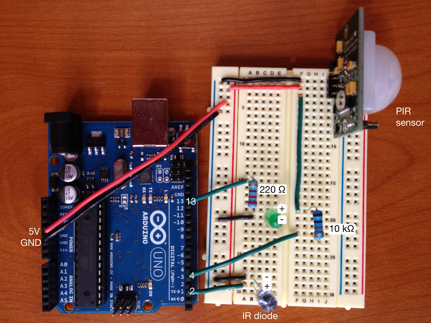
The full circuit can be seen by clicking on the photo above. In short, run wires from 5V and ground to the outside tracks on the breadboard. Connect Arduino pin 2 to the the positive lead on the infrared diode, with the negative lead connected to ground on the breadboard. For the PIR sensor, run a wire from the negative rail on the breadboard to the GND (left) terminal, run a second wire from the positive rail on the breadboard to the VCC (middle) terminal, and run a third wire to a 10 kΩ resistor. Connect the other side of the resistor to Arduino terminal 4. Last, run a wire from Arduino terminal 13 to a 220 Ω resistor, which connects to the positive lead on an LED; connect the negative lead on the LED to the ground rail on the breadboard. The LED circuitry is optional, but it lets you see when the camera is being triggered, since there is no way to see whether the IR LED is actually firing.
The Arduino commands have several functions. pulseON sends an infrared pulse of the correct duration, pulseOFF halts the infrared signals, and takePicture sends the correct series of pulses and halts to trigger the D80 shutter. The loop function is set to trigger a picture whenever the sensor goes from a state of no motion detected to one of motion detection. A minimum of 5 seconds between photographs is set, and this can be varied.
Get the D80 ready to receive infrared signals by repeatedly pressing the multishot button (adjacent to the AF button on the top of the camera) until the infrared remote icon appears (it looks like a rectangle with a circle inside at one end). The D80 has a infrared remote timeout, so you’ll likely want to keep it on. To do that, go to Menu, Custom Setting Menu (the pencil icon), then go to Remote on duration, and set it to whatever time you would like. 15 minutes is the maximum.
Place the infrared diode near the small oval infrared sensor on the D80, just above the D80 label on the front right of the camera. Make sure the infrared sensor is facing the same direction as the camera lens. Copy and paste the Arduino code below into the Arduino window, compile, and run. If you move within 15 feet of the infrared sensor, you should see the red light inside the sensor turn on, the LED on the breadboard turn on, and the camera take a picture.
Here is the Arduino code:
// Based on http://luckylarry.co.uk/arduino-projects/arduino-motion-triggered-camera/
// The sequence of pulses needed appears to have been reverse engineered at http://www.bigmike.it/ircontrol/
// This is another useful site on the subject: http://www.bemasher.net/archives/114
int pirPin = 4; // digital pin 4 for PIR; put a 10k Ohm resistor between pin 4 and OUT on PIR
int ledPin = 13; // digital pin 13 for LED; put a 220 Ohm resistor between pin 13 and the LED
int IRPin = 2; // assign the Infrared emitter/ diode to pin 2; connect other lead of IR diode into ground
int noMotion = 1;
// pulse the infrared emitter for a specified duration (in microseconds)
void pulseON(int pulseDuration) {
unsigned long endPulse = micros() + pulseDuration; // calculate time when pulse should stop
int halfCycle = 13; // half a clock cycle for a 38 Khz (26.32 microseconds period) wave
while(micros() < endPulse) {
digitalWrite(IRPin, HIGH); // emit IR for half a cycle
delayMicroseconds(halfCycle);
digitalWrite(IRPin, LOW); // stop emitting for half a cycle
delayMicroseconds(halfCycle);
}
}
// stop pulsing the infrared emitter for a specified duration (in microseconds)
void pulseOFF(unsigned long delayDuration) {
unsigned long endDelay = micros() + delayDuration; // calculate time when delay is over
while(micros() < endDelay);
}
// sequence of pulses for taking a picture on a Nikon D80 camera
void takePicture() {
for (int i=0; i<2; i++) {
pulseON(2000); // pulse for 2000 microseconds,
pulseOFF(27850); // then off for 27850 microseconds,
pulseON(390); // on for 390 microseconds, and so on
pulseOFF(1580);
pulseON(410);
pulseOFF(3580);
pulseON(400);
pulseOFF(63200);
} // loop the signal twice.
}
void setup() {
pinMode(pirPin, INPUT); // set PIR pin as input
pinMode(ledPin, OUTPUT); // set LED pin as output
pinMode(IRPin, OUTPUT); // set pin as output
}
void loop() {
if(digitalRead(pirPin) == HIGH) {
// motion detected
if (noMotion == 0) {
// take picture only if coming from a state of no motion
digitalWrite(ledPin, HIGH);
takePicture();
noMotion=1;
delay(5000); // wait 5 seconds between pictures
}
} else if(digitalRead(pirPin) == LOW) {
// No motion
digitalWrite(ledPin, LOW);
noMotion=0;
}
}