The world’s my home when I’m mobile
Pete Townshend
The world’s my home when I’m mobile
Pete Townshend
ARDUINO: TAKING THE WEATHER MONITOR ONLINE
01/13/2013
The weather monitor I made has been useful for keeping an eye on conditions in our basement, which can feel a bit damp at times. We just added a dehumidifer and I have been curious to track how it is working. The serial monitor on the Arduino is fine, but I have to go downstairs to see the humidity in the basement. It would be more useful to know this from anywhere. Luckily, its easy to turn an Arduino into a web server. As a side benefit, I can also have the Arduino log the data.
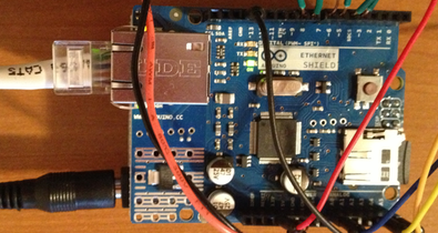
The ethernet Arduino shield is perfect for this job. It also comes with a microSD card slot, which could be used for serving up files for the web, but it I will use it for data logging. I bought my shield at the local RadioShack for about $46, but you can also get it from SparkFun or MakerShed.
The Arduino tutorial for setting up the shield as a webserver was the easiest I found. The first steps are to include the necessary libraries, declare the MAC address, declare the IP address, and specify the port. All of this is done at the top of the Arduino sketch.
#include <SPI.h>
#include <Ethernet.h>
byte mac[] = { 0xDE, 0xAD, 0xBE, 0xEF, 0xFE, 0xED };
IPAddress ip(192,168,1, 177);
EthernetServer server(80);
The line beginning "byte mac..." is where you enter the MAC address of your Ethernet shield. The MAC address consists of six two-character codes. For my shield, this code was printed on a sticker on the shield’s box. The line should start with 0x and follow with two-character codes that came with your shield. The ip() command is where you specify the IP address, and this will depend on the details of your home network. Be sure you do not specify an address already being used by another computer or printer. I used ping in the terminal to test the ip address I wanted, just to make sure that I did not get a response, meaning that that address is available:
ping 10.0.1.17
The server() command is where you specify the port that you will use for your server. By default, this is set to the standard html port of 80, but you can set this to whatever port you want, provided it is not being used by another service. Many websites (for example) list the ports and what they are used for. They also show which ports are open and free to use. One advantage of setting this to a non-standard port is that it offers a little more security than using the standard port.
You will need to add two lines to the setup() function to enable the webserver.
Ethernet.begin(mac, ip);
server.begin();
The first line starts the Ethernet, declaring the MAC address of the shield and its IP address. The second command, server.begin(), starts the web server. To make the server do something useful, we will modify the loop() command. The Arduino tutorial lists a more complex example, but at a minimum, you need to add a function like I show below (listenForEthernetClients), which will do all the ethernet work:
void listenForEthernetClients() {
EthernetClient client = server.available();
if (client) {
Serial.println("Got a client");
boolean currentLineIsBlank = true;
while (client.connected()) {
if (client.available()) { \\ send a reply
char c = client.read();
if (c == "\n" && currentLineIsBlank) {
client.println();
client.print(degreesC,0);
client.print(", ");
client.print(relativeHumidity,0);
client.print(", ");
client.print(millibar,0);
break;
}
if (c == "\n") { \\ starting a new line
currentLineIsBlank = true;
}
else if (c != "\r") { \\ a character on the current line
currentLineIsBlank = false;
}
}
}
delay(1); \\ give browser time to receive data
client.stop(); \\ close the connection
}
}
By modifying this function, you can make the web server do considerably more complicated things.
The first things this code does is determine whether the server is available, whether it is connected, and whether it is available. If all of that is true, it code reads from the server until it finds a blank line with an end-of-line character. If it finds that, then it can return text. The Arduino site tutorial shows how to return true html; here, I just want to return text. Be sure to begin with client.println(), which prints a blank line, then you can return with your text. Here, I am printing the temperature, humidity, and pressure, each separated by a comma and a space. If you are customizing your own web server, you only need to change the lines that begin with client.print; all the rest is fine as is.
At this point, a browser on your home network can access your Arduino, and it will report back the conditions. In your browser’s address bar, type xxx.xxx.xxx.xxx:yyyy, where the x’s are the IP address you specified in your Arduino sketch, and the y’s are the port number you specified. In my case, I used 10.0.1.15:1387. If you use the default port (80) for your server, you can use just the IP address. If you type the address and port number in my browser, you will get a bare-bones display of three numbers separated by commas. You can make the output as complicated as you like by writing more html code in your Arduino sketch. In my next blog post, I am going to take advantage of the stripped-down approach by writing an iOS app that will take those values and show them in a nicer format.
At this point, I can see the basement weather from anywhere I can reach my home wi-fi signal. That is better than standing in front of my Arduino’s LCD display, but not much. I would like to access the Arduino from anywhere, and to do that, I need to see behind my router.
To make the Arduino visible on the web from beyond my home network, you need to configure your home network. I have Apple’s Airport Extreme for my wireless network, and the Apple Airport Utility makes setting up this access easy.
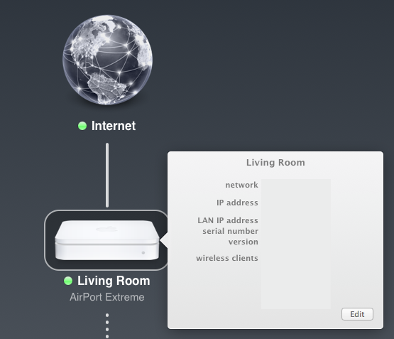
First, log into your home network, and you should see a display like this, which shows how you are connected to the network and the various base stations you have set up:

Click on the base station that is directly connected to the internet; for me, that is the Living Room Airport Extreme. You will see a display that describes your set up (I have blanked out the values of mine, for privacy):
Click the Edit button in the bottom right corner of that window, which will take you to the set up configurations, then click the Network tab:
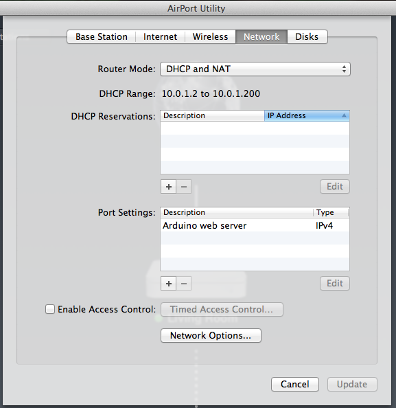
We will want to add an entry under Port Settings. Here, you can see I have already entered one for the Arduino. To add an entry, click on the plus sign under Port Settings, which will bring up another window:
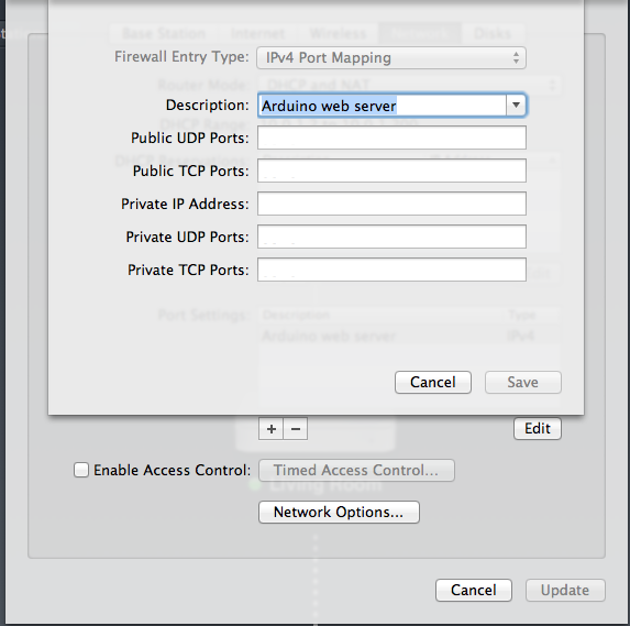
In here, set the Description to something informative (like Arduino web server), then set the Private UDP Ports and Private TCP Ports to the port you specified in your Arduino sketch. Set the Private IP Address to address you specified in your Arduino sketch; it will have a format like xxx.xxx.xxx.xxx. For the Public UDP Ports and Public TCP Ports, it is simplest to set these to the same value of as the Private ports. You can pick a different value if you want to hide which port you are using; search the web for port mapping for more background on this. We will just go with the easiest setting. Press save, and keep pressing save for the other windows, and eventually your base station will be set up with the new configuration. This might take a minute or two.
The shield also comes with a tiny slot that will hold a Micro-SD card, which will also let us use the shield as a data logger. Using the Micro-SD card requires two steps. First, initialize the card, then add logging to the loop() in our Arduino sketch.
The Ladyada site has a useful tutorial for initializing the Micro-SD card on this shield, and only a few modifications are needed because of changes to one of the example sketches. The first step is to download and install the latest version of SdFatLib. Installing it means placing the SdFat directory inside the Arduino/Library directory. Read the readme.txt and QuickStart.txt files from the download for more instructions. Restart the Arduino app to make sure it sees the updates.
The Ladyada tutorial says you should run the SdFatInfo example sketch, but this appears to now be called the SdFormatter sketch. You can get to it by going to Files ... Examples ... SdFat ... SdFormatter in the Arduino menu. Search for the line
if (!card.init(spiSpeed, chipSelect)) {
and change it to the following:
pinMode(10, OUTPUT); \\ set the SS pin as an output (necessary!) digitalWrite(10, HIGH); \\ but turn off the W5100 chip! uint8_t r = card.init(SPI_HALF_SPEED, 4); \\ Use digital 4 as the SD SS line
Run the sketch as in the Ladyada tutorial and your output should look like what they report if you are successful in formatting the card.
Now that the card is formatted, go back to the Weather logging sketch and add the code so that you can log your data. Do this by adding the following lines to the beginning of the sketch, above any of the functions:
#include <SdFat.h>
SdFat sd;
SdFile myFile;
const int chipSelect = 4;
We will want the logging at regular intervals, so also add this:
long lastReadingTime = 0;
long pauseBetweenReadings = 60000; \\ 60 seconds between data reading/recording
In the setup() function, add the following:
Serial.begin(9600); \\ SD card setup
while (!Serial) {} \\ wait for startup
// Initialize SdFat or print a detailed error message and halt
// Use half speed like the native library.
// change to SPI_FULL_SPEED for more performance.
if (!sd.begin(chipSelect, SPI_HALF_SPEED)) sd.initErrorHalt();
// open the file for write at end like the Native SD library
if (!myFile.open("data.txt", O_RDWR | O_CREAT | O_AT_END)) {
sd.errorHalt("opening data.txt for write failed");
}
// if the file opened okay, write to it:
Serial.print("Writing header to data.txt");
myFile.println("degreesC, relativeHumidity, millibar");
// close the file:
myFile.close();
This will start up the the Serial interface, then start up the sd card, create a file called data.txt, write a header to it, and finally close it.
The entire loop() function will now be fairly short, and the real work will be done in the functions that it calls. Setting things up this way makes the flow of the loop() function clearer.
void loop() {
if (millis() - lastReadingTime > pauseBetweenReadings) {
getData();
lastReadingTime = millis(); \\ record time of reading
writeDataToCard();
}
listenForEthernetClients(); \\ listen for incoming Ethernet connections
}
The loop will get the clock time, and if a sufficient time has elapsed since the last reading, it will get the data from the sensors, write it to the SD card, and write it to the serial port (which can be useful for debugging). Regardless of whether sufficient time has elapsed, the loop() function will always be listening for an ethernet connection.
The writeDataToCard() function handles all of the SD card writing:
void writeDataToCard() {
if (!myFile.open("data.txt", O_RDWR | O_CREAT | O_AT_END)) {
sd.errorHalt("opening data.txt for write failed");
}
myFile.print(degreesC);
myFile.print(", ");
myFile.print(relativeHumidity);
myFile.print(", ");
myFile.print(millibar);
myFile.println();
myFile.close();
}
It checks to see if it can open the data.txt file, and if it can, it writes the results, separated by commas and spaces, and followed by a newline. After writing one line, it closes the file.
We could set up the webserver to deliver all of the logged data from the MicroSD card, but for now, we will just remove the card and read it directly onto our computer, where it can be read as a comma-delimited file.
Here is a complete copy of the Arduino sketch.
Enjoy your access to your Arduino and all of the data you are now recording!