DIY ARDUINO BOARD
1/17/2015
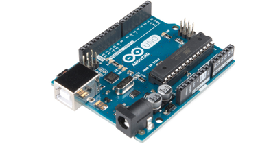
Arduino boards have come down in price, but you can make your own for about $10. It’s pretty simple, and it’s a good way to learn how an Arduino board works.
There are several tutorials on the web, in varying levels of detail. The one on the Arduino site is one of the clearest, and it was my starting point. It’s missing an important detail, and I’ll get to that later.
I built mine on two breadboards. One holds the Arduino microprocessor, and one holds the USB–serial adaptor needed for programming the board. Once the microprocessor has been programmed, you can disconnect the serial adaptor board. Since the serial adaptor is the most expensive part, you can buy just one of those and use it to program your Arduino boards as needed.
The most expensive parts are the microprocessor (about $5) and the breadboard (about $5). I used a microprocessor with the bootloader already installed. Microprocessors without the bootloader are about a dollar less, but take more work to set up initially. You will need:

The first step is to build the power supply, as the microprocessor needs regulated 5V power. The voltage regulator has three pins. As you read the writing on the face, the pins are (from left to right): input, ground, and output. A 9V battery will serve as the power source, with one of the 10 uF capacitors connecting input to ground, just to the left of the power regulator. The other 10 uF capacitor connecting output to ground and it straddles the power and ground rails on the breadboard. The pins on the capacitors are long, so trim them to keep the capacitors close to the board. This is true for all of the LEDs, resistors, and capacitors: trim the leads so the components don’t tower over the board like a scene from War of the Worlds. These capacitors are electrolytic, so remember to keep the negative side of the capacitors (the side with the silver stripe) connected to the ground pin, with the other side receiving positive voltage.
The voltage regulator will convert the 9 volts to 5 volts, which will be used to power both sets of rails for the breadboard. The excess voltage is converted to heat, but the heat generated is minor and no heat sink will need to be added to the voltage regulator. The two capacitors dampen any voltage fluctuations on either the input side or the output side of the voltage regulator.
With wire, connect the ground pin of the voltage regulator to the ground rail of the breadboard, and connect the output pin of the voltage regulator to the positive rail. Throughout, I follow the convention of using red wire for positive voltage and black wire for ground.
With wire, connect the input and ground pins of the voltage regulator to the opposite side of the breadboard channel. The 9 V battery will be connected adjacent to these wires. Although they aren’t necessary, they’re visual reminders of how to connect the battery.
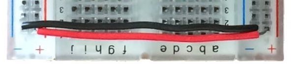
Next, use wire to connect the positive and negative rails on opposite sides of the breadboard, at the bottom. This will provide a steady 5 volts anywhere along the breadboard.
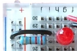
Near the top of the breadboard, opposite the power supply, connect an LED. From its positive (longer) lead, connect it to the 5 V rail with a 220 ohm resistor. Connect the negative (shorter) lead to the ground rail with some wire. This LED will glow when the breadboard is supplied with power. Because it is on the opposite rail from the voltage regulator, it confirms that the entire breadboard has power.
This is a good point to test the circuit by connecting the leads from the 9 V battery to the input and ground of the voltage regulator. The LED should light up. Use a volt meter to test that the input pin of the voltage regulator is at approximately 9 V and the output pin is at 5 V. Also, confirm that the positive lead of the LED is receiving 5 V. If everything is ok, disconnect the battery from the breadboard.
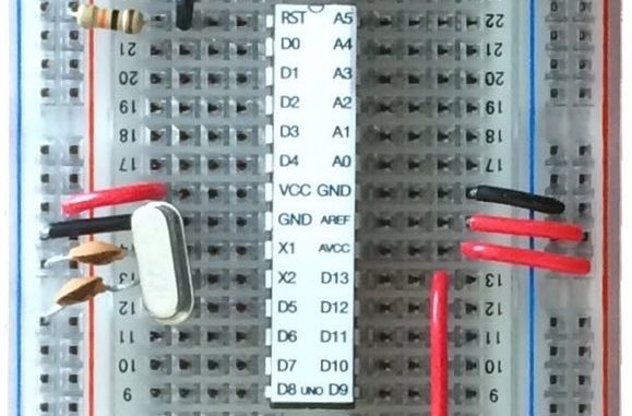
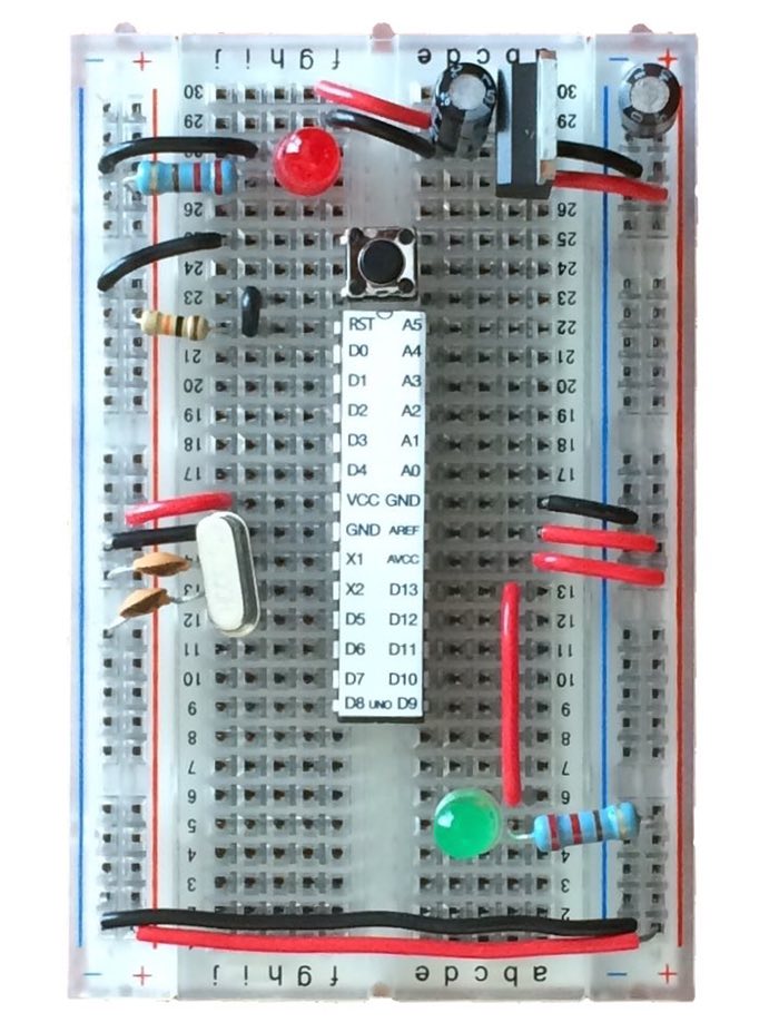
Next, add the microprocessor and make its connections. Place the ATmega328 microprocessor so that it straddles the center channel of the breadboard, with the dimple facing towards the voltage regulator. Gently push the microprocessor into place, taking care not to bend any of its pins.
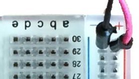
The pins on the microprocessor, like any chip, are numbered starting at #1 to the left of dimple (left top in the picture). The pin numbers increase down the left side to #14. The numbers resume at the bottom right of the chip at #15 and increase towards the top, ending at #28. I like this particular microprocessor from Sparkfun because they attach a label to the top with the pin names.
Use a 10k ohm resistor to connect the RST (reset) pin (#1) to the 5V rail of the breadboard. This is a pull-up resistor which will maintain a positive 5 V on the reset pin. The reset pin is triggered whenever voltage on that pin goes to zero, and the pull-up resistor insures that the pin voltage doesn’t inadvertently drift to zero.
With wire, connect the VCC pin (#7) to the 5 V rail, and connect the GND (#8) to the ground rail.
Use the two pins on the 16 MHz oscillator to connect the X1 (#9) and X2 (#10) pins. All microprocessors run on a clock, and this oscillator provides that timing for the ATmega microprocessor. Use the two 22 pF capacitors to connect each of these pins to the ground rail. These ceramic capacitors do not have a positive or negative side, so they can be inserted either way.
On the right side of the microprocessor, use wire to connect GND (#22) to the ground rail, AREF (#21) to the 5 V rail, and AVCC (#20) to the 5 V rail.
The AREF pin and the AVCC pin are both related to analog inputs for the Arduino. The Arduino is capable of reading an analog voltage and converting it to a digital signal with its Analog-Digital Converter (or ADC). To do this, it needs a reference voltage for the 5 V that the Arduino is receiving, which is supplied by the AREF pin. The AVCC pin supplies the voltage for the ADC. To make the ADC work at a basic level, both of these pins can simply be connected with wire to the 5 V rail. Slightly more complex wiring is needed for more precise analog-digital conversion, which will handle variations in the supplied voltage.
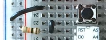
Place the small pushbutton switch immediately above the microprocessor. The silver leads should be on the outside (not top and bottom) of the button. Use a short segment of wire to connect the bottom button lead to the reset (#1) pin on the microcontroller. Connect the top button lead to the ground rail with some wire. Pressing this button will allow the voltage on the reset pin to go to zero, resetting the microprocessor. The pull-up resistor prevents a short circuit when the reset button is pressed.
The Arduino is completely wired in at this point. Before we can use it, we need a way to load sketches onto the microcontroller.
The parts list for the serial adaptor board is shorter, but it is more expensive (the red breakout board costs about $15). Because the serial adaptor board is needed only to load sketches onto the Arduino, you could have many Arduino boards, but only one serial adaptor board, which could be connected and disconnected to each board when a sketch needed to be loaded. You will need:
First, solder a strip of header pins to either side of the breakout board. Be sure to have the pins under the breakout board and solder them on the upper side (the side with the chip and micro USB connector).
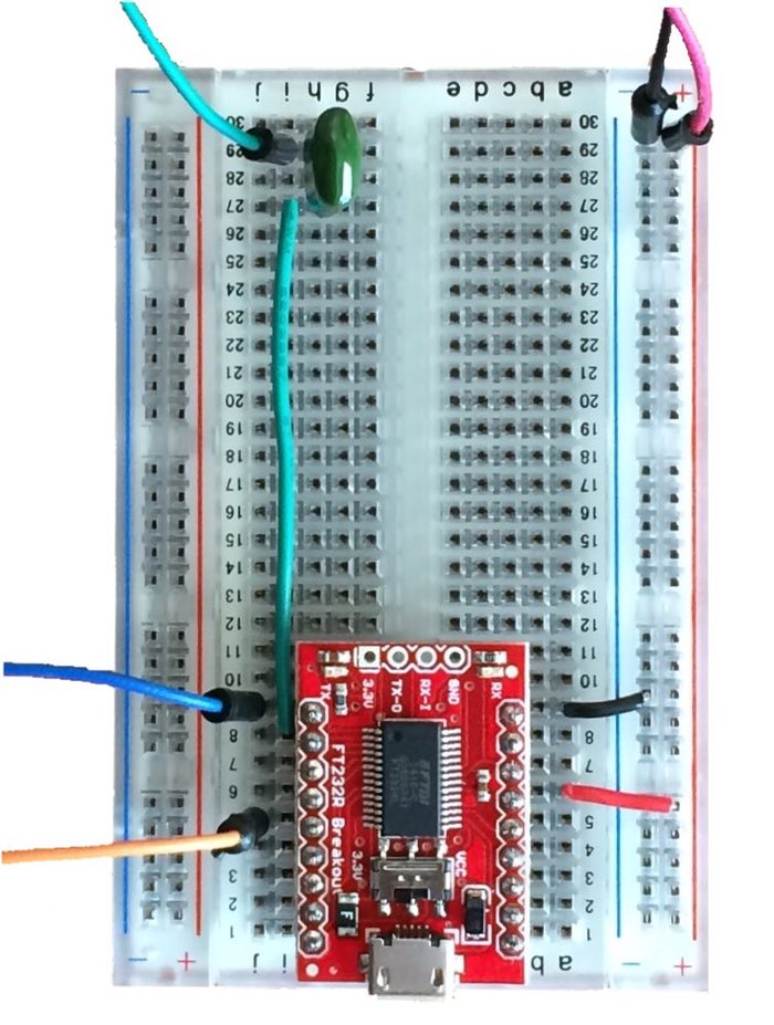
Place the breakout board near the edge of the breadboard, straddling the center, with the USB plug at the edge of the board. Take care not to bend the header pins as you insert the board.
On the right side of the board, connect the top pin (GND) to the ground rail, and connect the fourth pin (VCC) to the power rail. The pins are named on the bottom of the breakout board.
On the left side of the board, connect a wire to the top pin (TX) and a wire to the 5th pin (RX). These will be connected to the TX and RX pins of the microcontroller (TX to RX, RX to TX).

Connect a wire to the second pin (DTR) and attach it near the top of the board. Insert the 0.1 uF capacitor to this far end of the wire. This mylar capacitor doesn’t have a positive or negative side, so it can be inserted in any direction. Connect connect a second wire to the other leg of the capacitor. The free end of this will be connected to the reset pin of the Arduino board. I’ll explain how this capacitor works when the boards are connected.
Finally, connect a wire to the positive and negative rails on the right side the breadboard, the same as the power and ground for the breakout board. These will be connected to the power and ground rails of the breakout board.
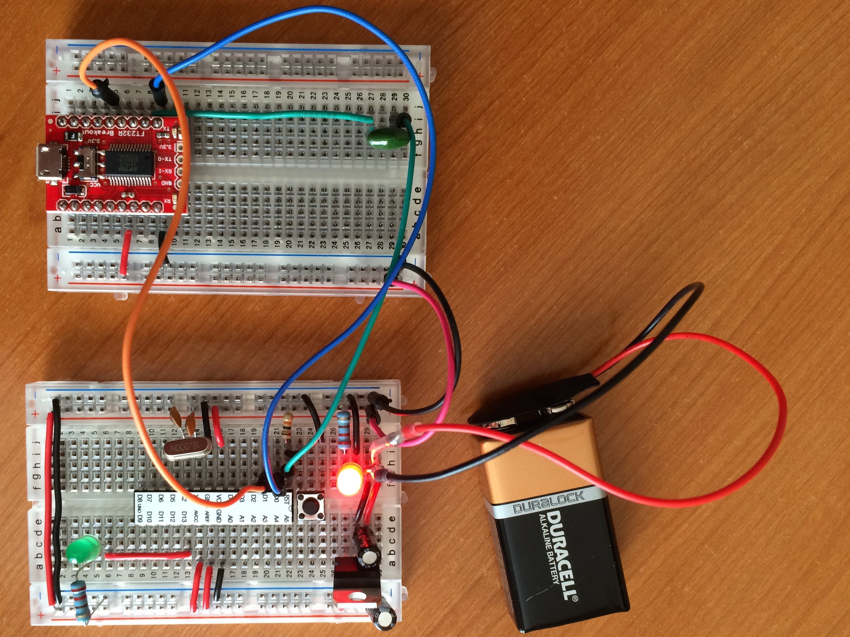
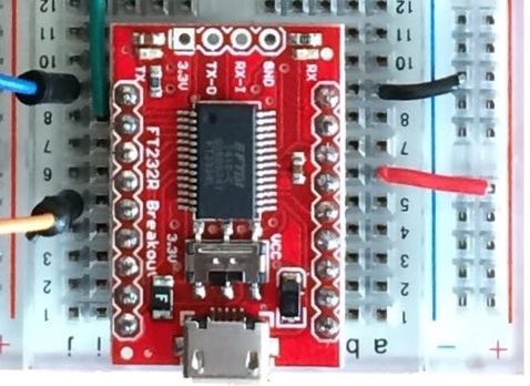
Connect the 5V (red) and ground (black) wires on the serial adaptor board to the 5V and ground rails of the Arduino board.
Connect the TX (blue) wire on the serial board to the D0 pin (#2) of the microprocessor. Connect the RX (orange) wire on the serial board to the D1 pin (#3) of the microprocessor. The blue and orange wires carry the serial commands between the serial board and the ATmega microprocessor.
Connect the DTR (green) wire on the serial board to the RST pin (#1) of the microprocessor. The green wire will allow the serial board to automatically reset the ATmega microprocessor when uploading a new sketch. Not having this would require you to press the reset button at a specific point when uploading a sketch, an act that takes a certain amount of timing. This is what is missing from the tutorial on the Arduino website, and it took awhile to find the solution.
The mylar capacitor along the green line is critical for this reset function to work. The DTR pin is on when the breakout board is supplied with power, which you can test by connecting an LED to it. Thus the capacitor is receiving voltage from two sides. On the microcontroller side, it is receiving 5 V. The serial breakout board supplies 3.3 V. You can test both of these with a volt meter. Thus, the difference in voltage means the capacitor is normally charging. When the DTR pin is set, it’s voltage is turned off by the serial board, causing the capacitor to discharge and therefore bringing the voltage on the microcontroller reset pin to zero. The capacitor then recharges, bringing the voltage on the reset pin up. In this way, the act of turning the DTR pin to low causes the reset of the microcontroller. Without the capacitor, the reset pin would be held to zero voltage until the serial board unset the DTR pin (that is, returned the voltage to it).
Connect the 9V and ground leads from the battery to the input and ground of the voltage regulator on the Arduino breadboard. The LED on the breadboard should turn on. Testing with a volt meter should confirm that everything is receiving power. Disconnect the battery for the next steps.
The easiest way to test these boards is to run the Blink sketch included with the Arduino software.

Connect a wire to D13 (#19) and anchor the other end on a free row of the Arduino breadboard. Connect the positive (long) lead of an LED to that wire, and insert the ground (short) lead of the LED in another row. Connect the short lead to the ground rail of the breadboard with a 220 ohm resistor.
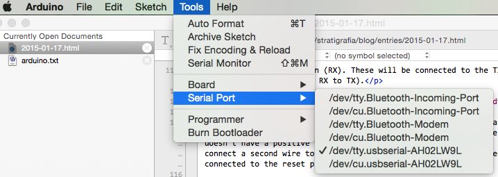
Launch Arduino on your computer. Go to File … Examples … 01.Basics … Blink. Plug the USB cable into your computer and the serial adaptor board. Your board should be set to Arduino UNO (Tools … Board … Uno) and your serial port should be set to something like /dev/tty.usbserial-AH02LW9L. The last characters may be different, but it should be tty and usbserial.
Upload the script, and the LED connected to D13 (#19) should blink. If it doesn’t, you may need to install the drivers for the usb-serial board. I did this, but I'm not sure if it was necessary. The drivers can be downloaded here.
Disconnect the five serial board wires from the Arduino board (red, black, blue, orange, and green). Connect the 9 V battery to the wires leading to the input and ground on the voltage regulator. The power LED and LED connected to D13 should still be working.
It works! Now go make something.