3D PRINTING
9/26/25
We use 3D printing to fabricate parts for a Jacob’s Staff, a tool used in geology. For several years, my graduate students handled the printing, and they each became skilled at it. Unfortunately, as each of them graduated, their knowledge was largely lost because it wasn’t written down. I set out to learn the whole process for myself and to document what we do.
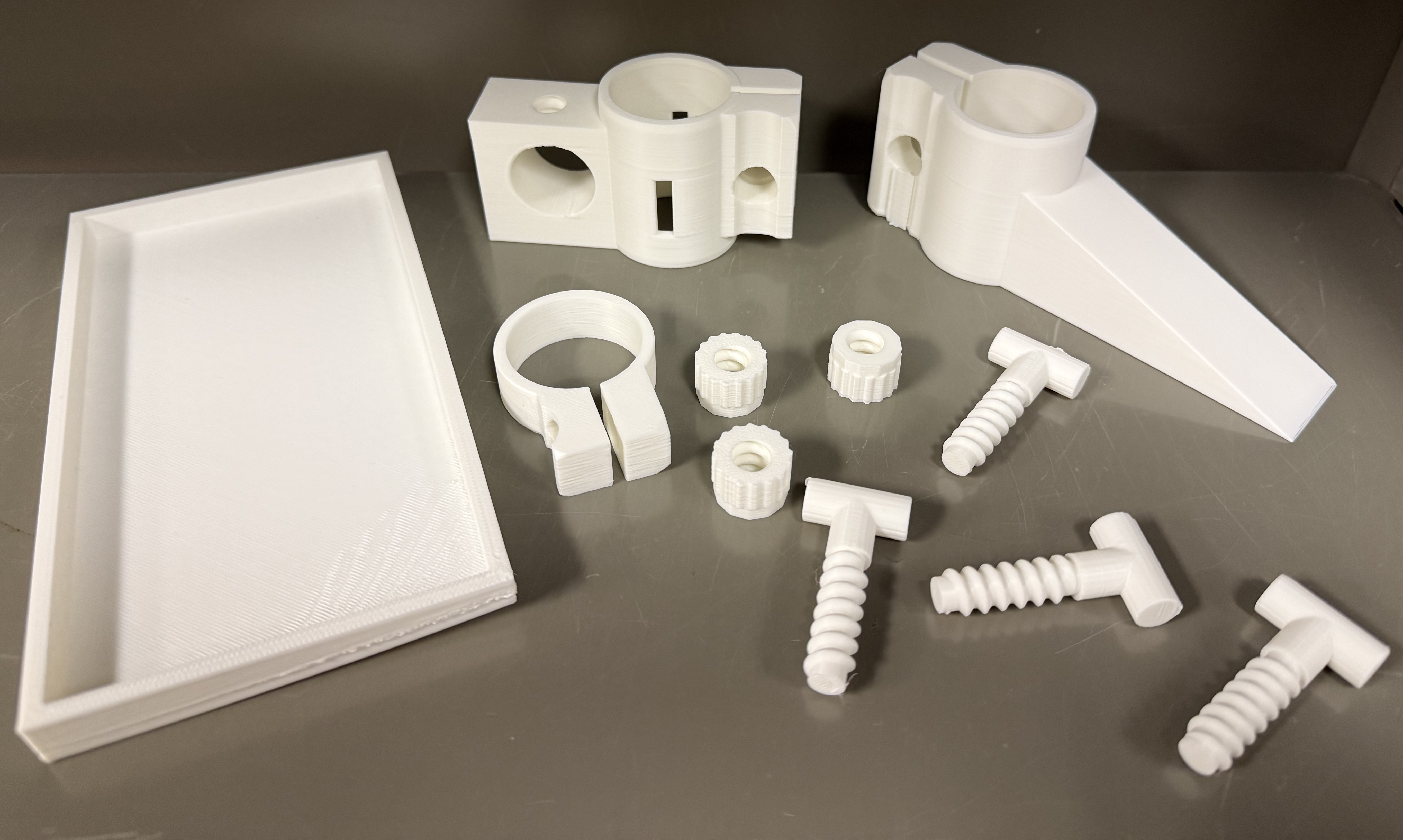
The Jacob’s staff consists of five types of parts: a cradle that holds the phone (left), a laser-pointer bracket (top center), a cradle bracket (top right), a support collar (just to the right of the cradle), four screws, and three nuts. The two main challenges in printing these are the type of filament required and the tendency for parts to warp or fail during printing. These problems can be severe, and at one point our success rate was as low as 20–25%. With the protocols below, the success rate is now greater than 95%.
After the initial setup, 3D printing is straightforward. Getting to that point can be complicated, so the post is long. Much of what follows, though, is considerations for the first few prints. I’ll cover five main considerations: choice of printer, choice of filament, bed adhesion, slicing, and printing.
Printer
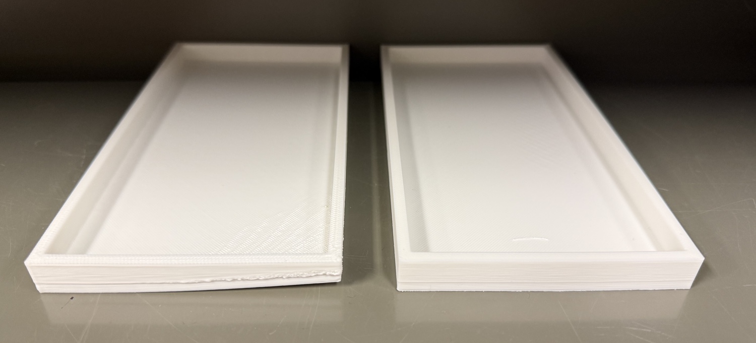
The number of 3D printers is daunting, and the models change frequently. What you want is one capable of printing ABS plastic (discussed below). ABS is finicky and prone to warping, which can result in a partially distorted print or even one that fails completely. Here are two phone cradles; the one on the right printed well, but the corner of the one on the left lifted from the bed early in the printing. Luckily, it resolved itself, and the print can still be used, although it isn’t ideal.
To minimize warping and curling, you want a printer that can achieve high uniform temperatures in the nozzle, on the bed, and in the chamber. Printers that have a fully enclosed chamber hold uniform temperatures much better than those that are open. Check the printer specs to make sure it can achieve bed temperatures of up to 110°C and chamber temperatures of up to 60°C. I also recommend getting a printer that has a flexible, removable plate above the bed; these adhere magnetically, and many have a coating that helps with adhesion. A removable plate also makes it easier to remove a print, and it lets you cool it down so that adhesives (discussed below) adhere better.
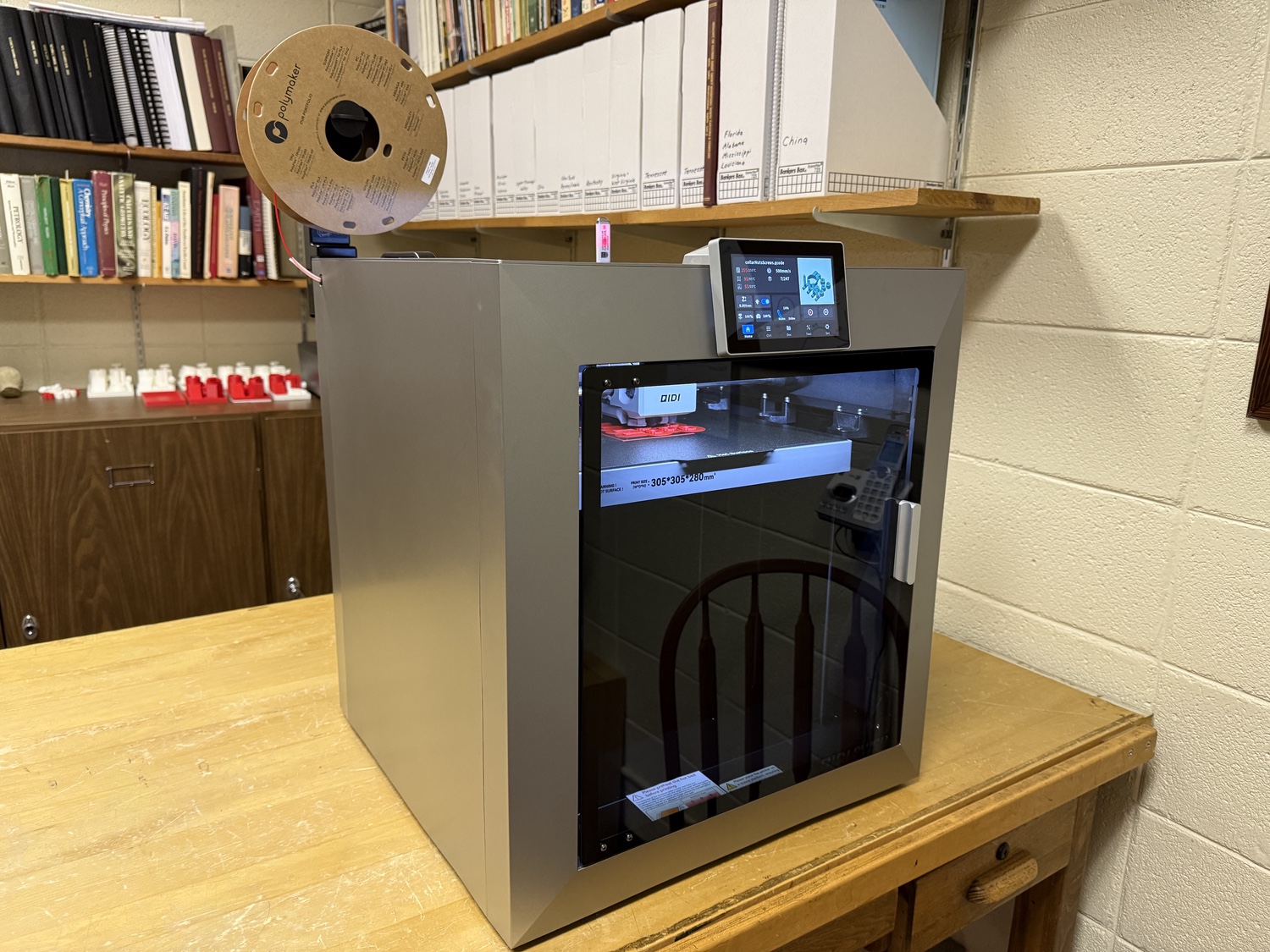
After poor success with a couple of printers available in our department, we purchased a QIDI Plus 4, and it works well. It cost about $799 in August of 2025 and is now $699. Advancements come quickly in the world of 3D printers, so it may well be replaced by another model when you read this.
Read plenty of reviews as you shop; I found the ones at Tom’s Hardware to be the most informative, thorough, and helpful. Many reviews only report the specs, which is much less helpful than someone who tests the printers.
Filament type
3D printers use plastic filament, which you purchase in spools, and it is the main consumable you will need for printing. PLA (polylactic acid) is the most widely used filament, because it is inexpensive, easy to work with, and makes few demands of a printer. We initially used PLA, but discovered in our first field season that it was highly prone to warping in the heat of field work. Not one of our five units survived the summer. Sometimes the parts (especially the phone cradle) would warp before your eyes, making you feel like you were trapped in Dali’s The Persistence of Memory. Steer clear of PLA.
Switching to ABS (acrylonitrile butadiene styrene) solved these issues. ABS is a tough, heat-resistant plastic used for things like motorcycle helmets and LEGOs. We have not been able to break parts made with it, despite trying hard (like hurling them against a cinder-block wall). None has warped either, even after being left on the sun-baked dashboard of a car.
ABS produces hazardous ultrafine particles during printing, and the smell is noticeable. Use your printer in a well-ventilated space.
ABS is widely available from several manufacturers. We use and like PolyLite ABS 1.75 mm diameter filament, which comes in 1-kg rolls. It comes in many colors, and I recommend white or a bright color like red or neon orange to make the parts easily visible if you drop them in the field. Light colors are also important because you want to keep the temperature cool, since your phone will sit in the cradle. The price of a roll varies with the color, but most are in the $20-$25 range. When our prints are mostly successful, we can print just over 5 complete Jacob’s staff assemblies from a single 1-kg roll.
Bed adhesion
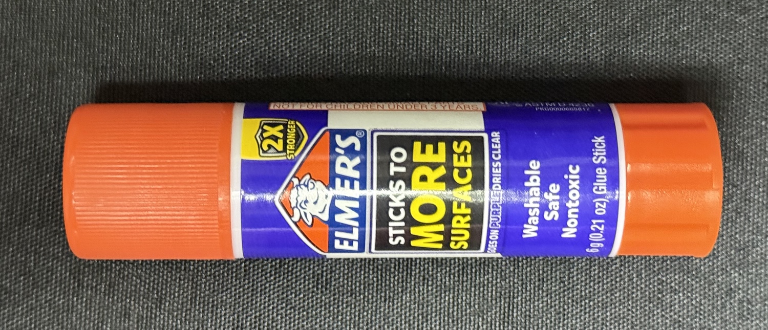
Adhesion to the bed is the other significant concern with ABS, and using an adhesive helps greatly. Gluestick can work well, such as the generic brand that came with the QIDI printer. However, I tried Elmer’s (the type that turns purple) and had my first truly failed print with this printer. Some people report success with it, so you might try it; it is cheap, about $2 a stick.
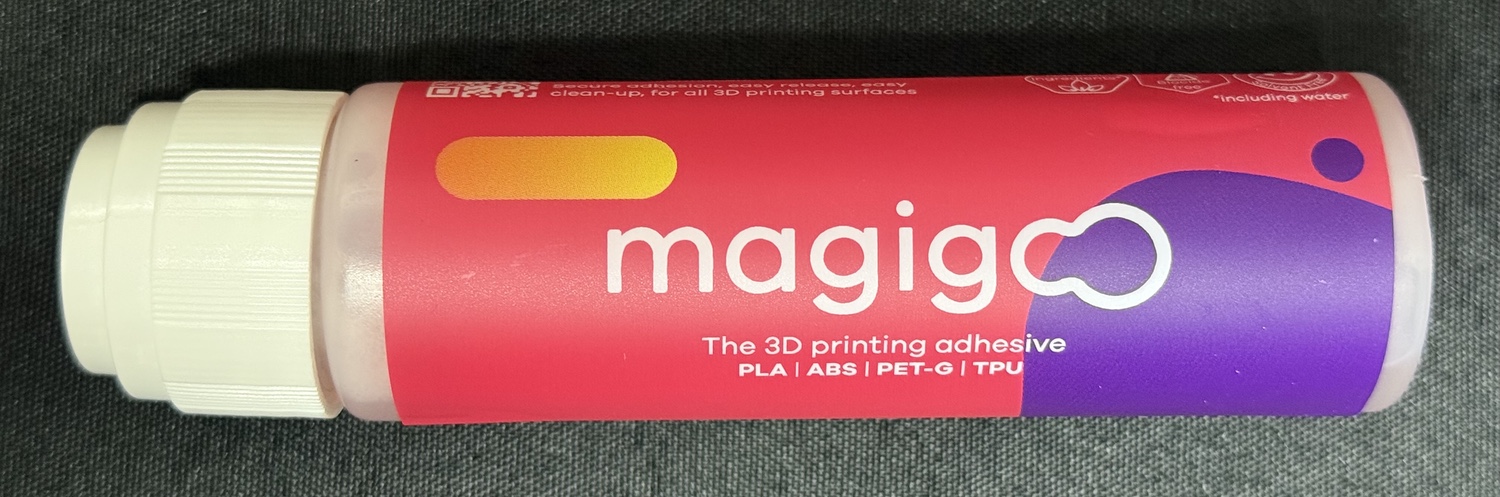
We now use Magigloo, which works great. It is activated by heat and deactivated by cooling, making it easy to detach prints from the bed. It also cleans easily with water. Magigloo is a bit pricy, about $20 a bottle, but the results are worth it.
Regardless of what adhesive you use, I recommend cleaning the bed after every print to prevent glue buildup. Cleaning the bed also allows it to cool off, making it easier to apply adhesive. A removable bed makes cleanup much easier.
Slicing
The shapes of the Jacob’s Staff parts (cradle, cradle bracket, laser bracket, support collar, screws, nuts) are described in .stl (stereolithography) files (download). These files break down the shape of an object into a series of tiny triangles.
The .stl files need to be converted into instructions for a 3D printer, which requires an app called a slicer. Because 3D printers construct an object from numerous thin layers of plastic, a slicer converts the .stl shape files into a description of where plastic should be placed in each of those layers, along with other printer-specific instructions. Many slicer apps are available, and our QIDI printer came with one. We have had success with Orca Slicer, which is free, open-source, and runs on Macs, Windows, and Linux. I chose Orca Slicer because it is well-recommended, and because my brother uses it, so I had someone to ask with the inevitable questions. Slicers allow you to export the printer instructions as a G-code (.gcode) file, which many printers require. G-code stands for geometric code, a standard format for instructions to 3D printers and similar manufacturing tools.
I’ll describe the steps for slicing .stl files using Orca Slicer; if you use another slicer app, the interface will look somewhat different, but the steps are the same.
First-time setup
You will need to do some one-time setup the first time you run your slicer. Launch Orca Slicer and click on the Get Started button in the window. Select your geographic region, and in the next window, enter your printer name in the search bar. You may need to know your nozzle size, so check your manual; our QIDI Plus 4 has a 0.4 mm nozzle. Select your printer, then click Next.
The next window lists many types of filaments. In the upper half of the window, uncheck the All box next to Filament Type and Vendor, then check the boxes you need for both of these (for us, ABS for Filament Type, and Polymaker for Vendor). For us, doing that displayed a single matching filament in the bottom half of the window. Click Next.
The next window was about Stealth Mode; I enabled it. Click Next.
The next window is for Proprietary Plugins. I left it unchecked. Click Finish.
You have just established the settings that will be used every time you slice an .stl file. You shouldn’t need to do this again unless you switch printers or filaments.
Creating a G-code file
The next step is to slice an .stl file and create a .gcode file we can print. You might need to do this only once, but you may have to redo this process if you decide later to adjust some settings.
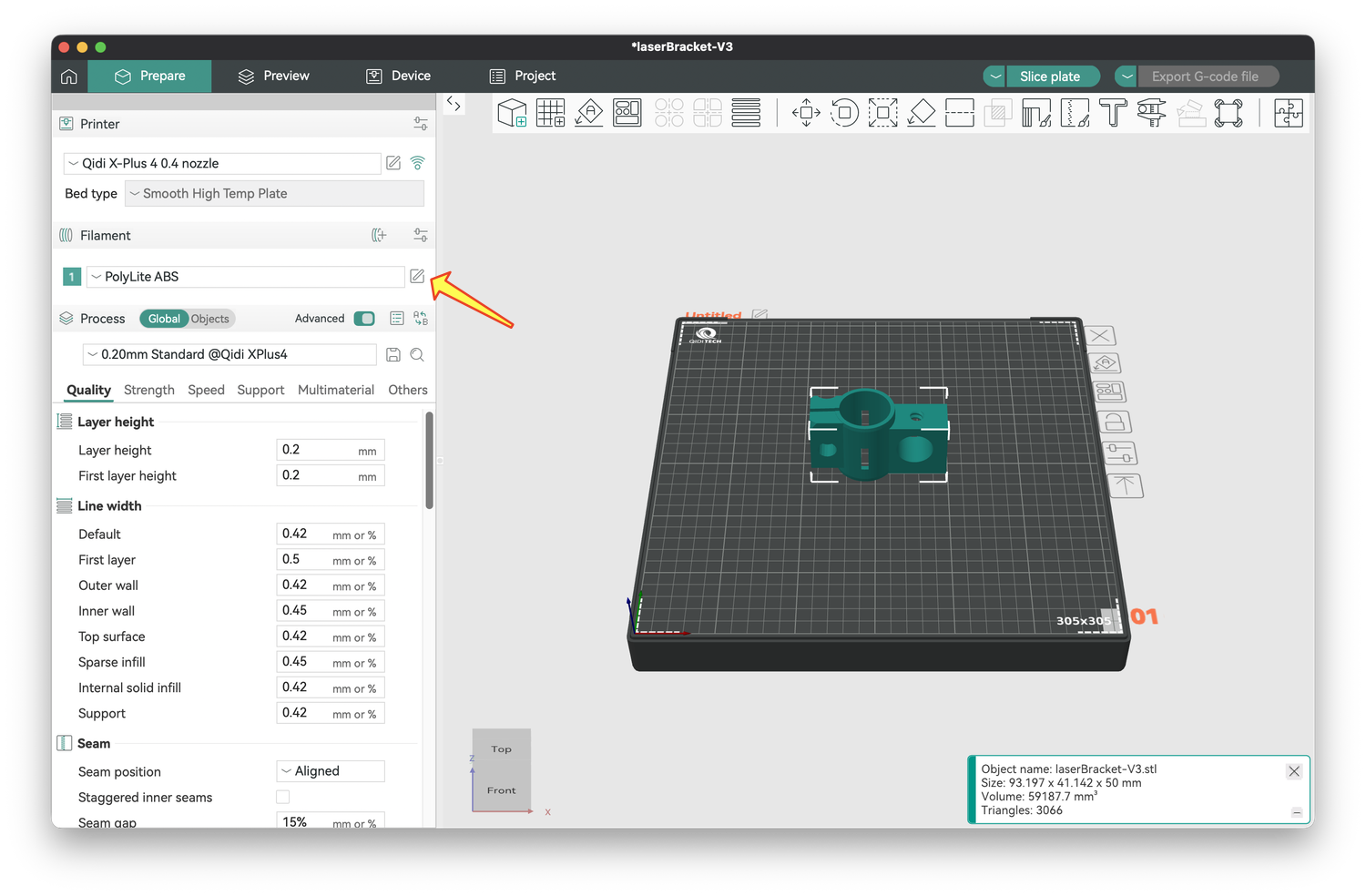
In Orca Slicer, click New Project, which will open a window with settings on the left and a gridded visualization of your printer bed on the right. Because you entered your printer, it knows the geometry of your printer bed. For example, mine correctly displays 305x305 (mm) in the lower right and QIDI Tech in the upper left of the printer bed. The bed is displayed as it would appear as you look into the printer. If you click and drag on the plate, you can reorient it to see it from different angles.

To add an .stl file, click the cube with the plus symbol (the orange arrow in the image above). In the window that opens, navigate to your .stl files and select one. Although you can add more objects and print them simultaneously (discussed below), we will print just one object for now.
Four modifications were needed to improve the prints.
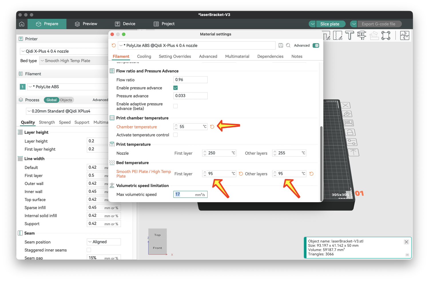
1) I needed to adjust the temperatures of the bed and chamber to be slightly different from the defaults to help with bed adhesion. To do this, click on the pencil in the square just to the right of your filament type (yellow arrow). The settings for bed and chamber temperature are listed under the Filament tab.
I lowered the chamber temperature to 55°C (as recommended by QIDI) and raised the bed temperature to 95°C throughout the print (arrows below). Note that these modifications are indicated in orange, and you can use the orange circular arrow next to undo these changes. Close the window to save your changes.
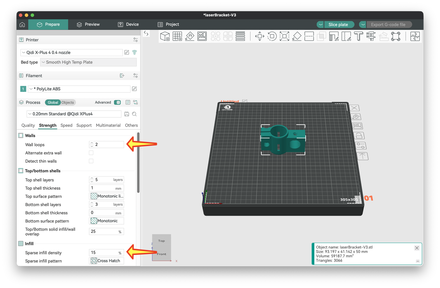
2) I made two modifications to make our prints stronger, and the settings for these are under the Strength tab (arrows below). The first was to double the number of solid plastic wall loops from 2 to 4. The second was to increase the strength inside the object, which is a lattice of plastic and hollow spaces. To give more plastic to the structure, I raised the infill density from 15% to 30%. You could raise this higher, but it will use more filament, and the print times will take longer. You want a balance between these and object strength.
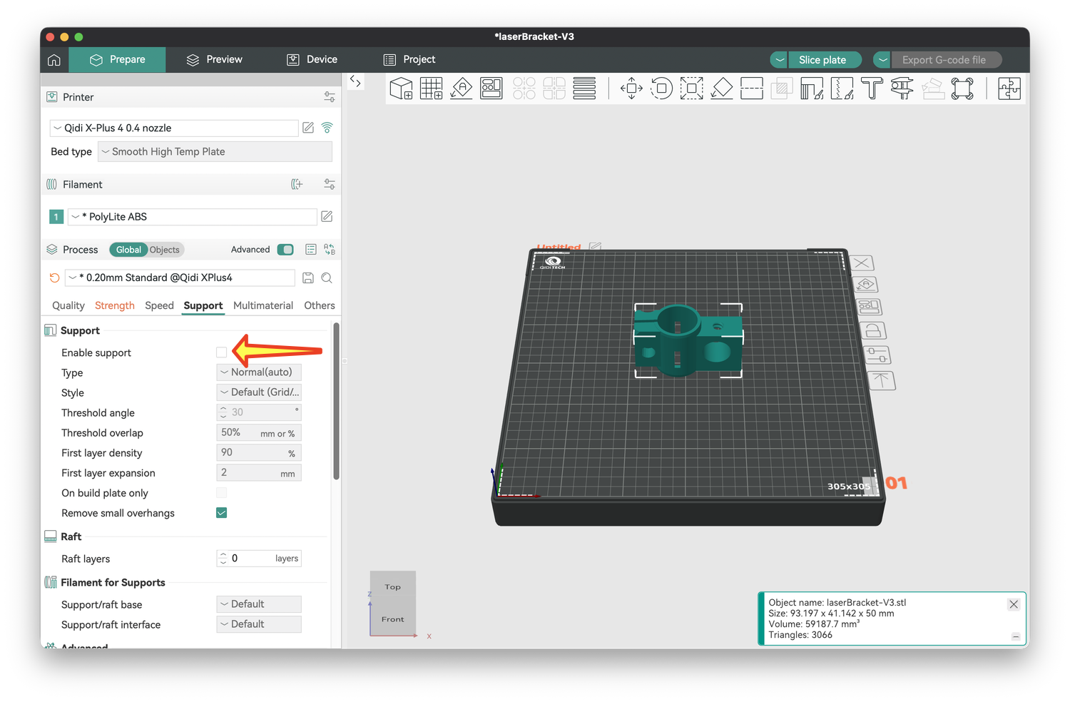
3) Some objects have empty spaces, and it helps to provide support, that is, something in those spaces for the plastic above the space to adhere to. The settings for this are under the Support tab. Check the box next to Enable support (arrow below).
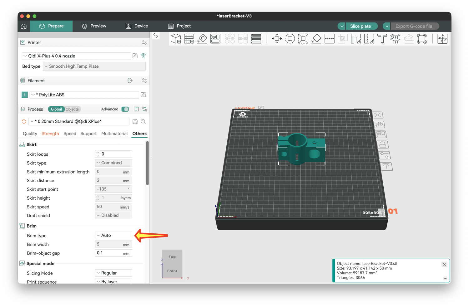
4) Some objects have a limited attachment to the bed, such as the nuts or vertically oriented screws. To increase their adhesion to the bed, you need a brim, a small area of detachable plastic that will surround these parts. The settings for this are under the Others menu. Next to Brim type, use the pulldown to change it from Auto to Outer Brim.
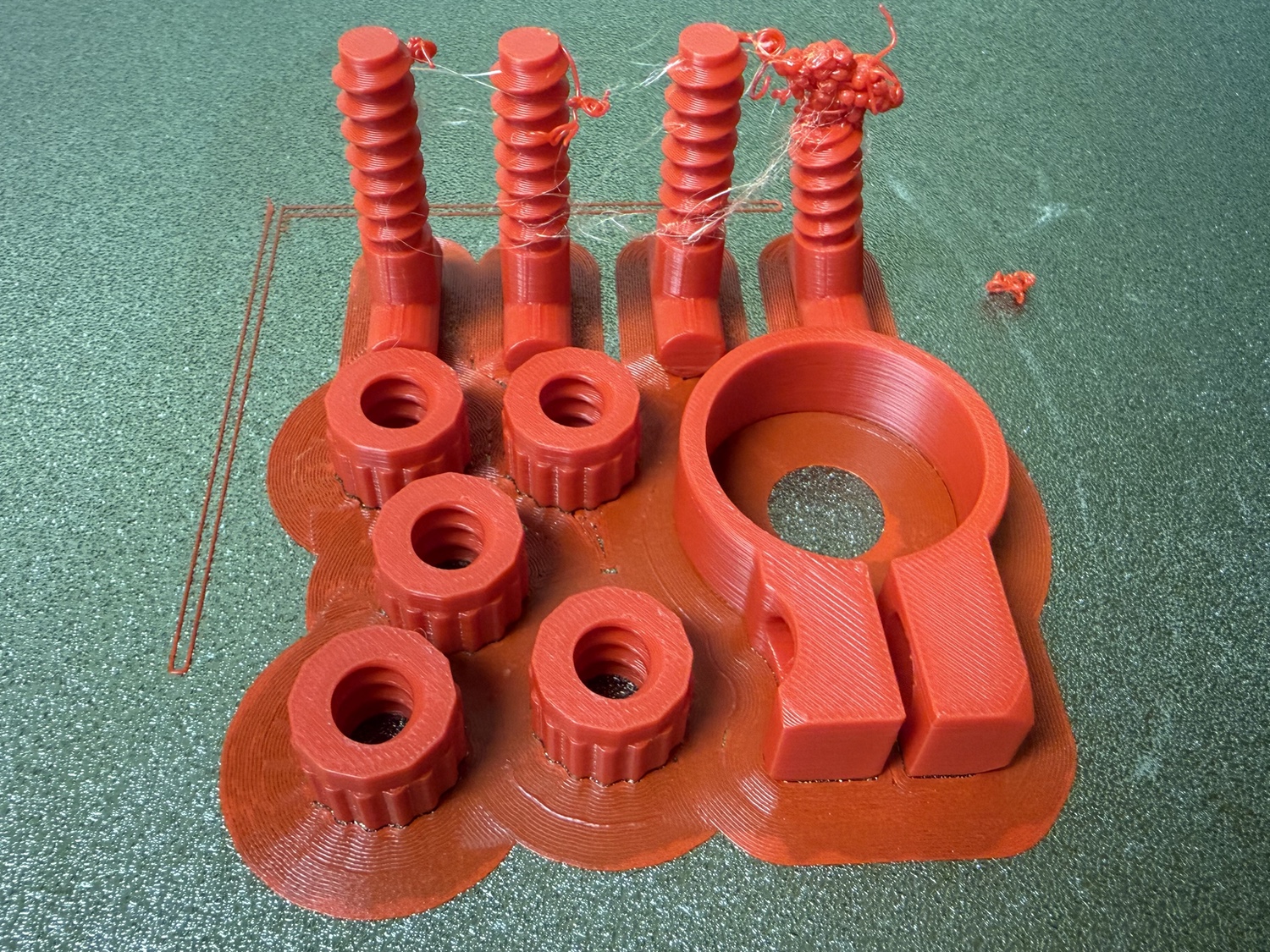
You likely won’t need a brim for large objects with a wide base. Small parts or ones that have a limited area at their base are most prone to adhesion problems. For us, the screws and nuts have the most common issues. As the screws become partly detached during printing, a formless blob of plastic accumulates at their end. I cut this off, and usually enough of the screw prints so that it can be used. I always add a brim when I print screws and nuts.
Once these modifications are made, you are ready to slice the model. Click on Slice Plate above the image of your bed and object (yellow arrow). If all goes well, you will not get a warning. If you do, follow the instructions and slice the plate again.
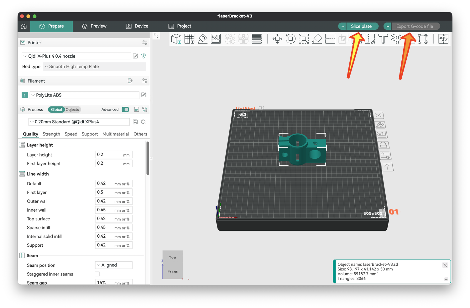
If slicing succeeds, the "Save as G-code" button will turn green. Click Export G-code file in the upper right (orange arrow), pick a name and location for your file, and click Save. This .gcode file is what the printer will use.
You can save all these modifications by saving the Orca Slicer file itself. This is useful if you ever want to modify the changes you just made, such as adding more support, changing the infill, or adding/removing a brim. Go to File ... Save Project, give your file a name and location, and click Save.
For each shape, there are now three files. The .stl file is the starting point; it just describes the shape of the object. The .3mf file is the Orca Slicer file, the intermediary for getting to the .gcode file. The .gcode file will be used by the printer. I recommend giving these similar names so it is clear that these are different files describing the same object, like laserCollar.stl, laserCollar.3mf, and laserCollar.gcode.
Printing multiple objects at once
You can print multiple objects at once, and this is useful for small parts. For example, I combine the support collar, four screws, and five nuts (two extras) into a single print. This saves time.
You might be tempted to combine all the objects into a single print if your bed is large enough. I have not tried this, primarily because the print time will become longer. Moreover, if the print fails, none of the parts may be completed, wasting time and money
To print multiple objects, add the first object using the square with the plus sign as described above. Add a second object the same way.
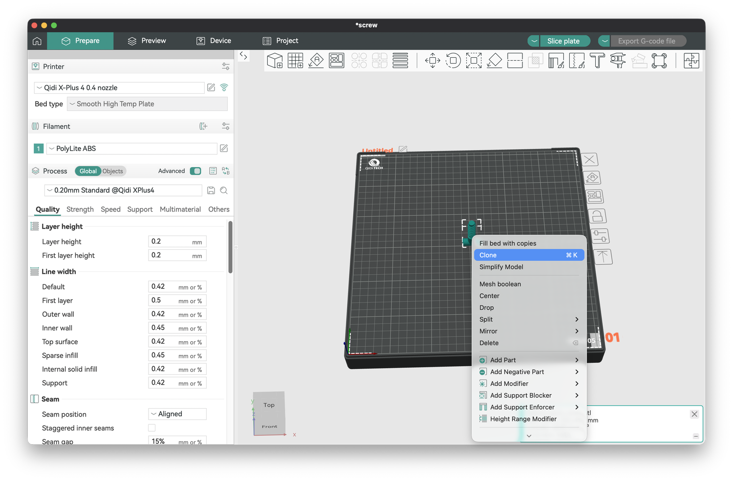
You can also clone an object by right-clicking (control-clicking) on it to bring up a floating menu. Choose Clone, enter the number of additional copies you would like, and they will be added to the printer bed. Sometimes these are placed too close to one another, and you can click and drag to move parts as necessary. You can also rotate a part by clicking on the rotate button above the print bed, which will let you rotate it around three axes: horizontal left-right (x), horizontal towards/away (y), or vertical (z). For example, the screws are added by default standing up (this is the most successful way to print them), but if you wanted them lying down, you could set x to 90°
After adding multiple parts, follow the instructions above to adjust the settings (temperature, strength, support, and brim), slice the plate, and export the .gcode file.
Printing
In comparison to slicing, printing is more straightforward. These instructions are specific to the QIDI, but your printer may have a similar approach. First, copy your .gcode files to a USB thumb drive, turn the printer on, and insert your thumb drive into the printer. Following the printer instructions, load a spool of ABS filament. You will likely just leave the spool on between prints. If you run out of filament mid-print, the print will pause, and you can load a new spool.
Next, remove the plate from the bed (if yours is removable) and apply adhesive evenly to the area that will be printed. Insert the plate and shut the printer door. Leave it closed during the print; a cool draft can cause ABS to warp, curl, or detach.
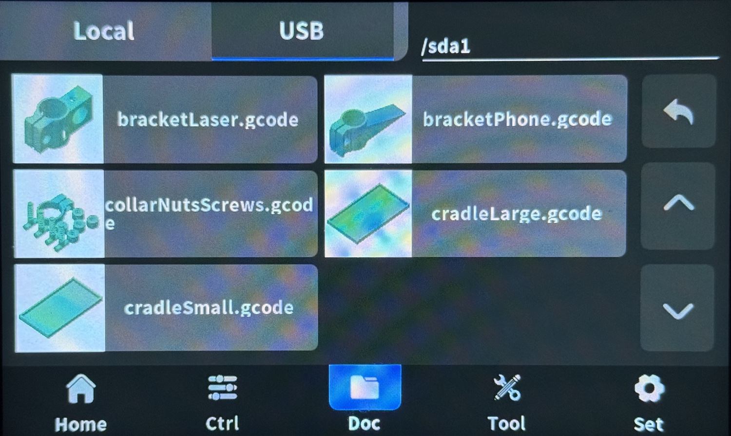
On the touchscreen, select the G-code file from the printer screen; you may have to navigate to your thumb drive, which is on the USB tab below.
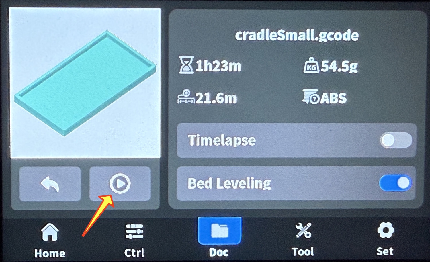
Once the file loads, tap on the home screen tab. This shows the estimated time to prepare the print (21.6 minutes), the time to print the object (1 hour, 23 minutes), and the weight of filament that will be used (54.5 grams). Tap the start arrow (yellow arrow) to begin the print. Although it will take more time, leave bed leveling on as it will help make a print successful.
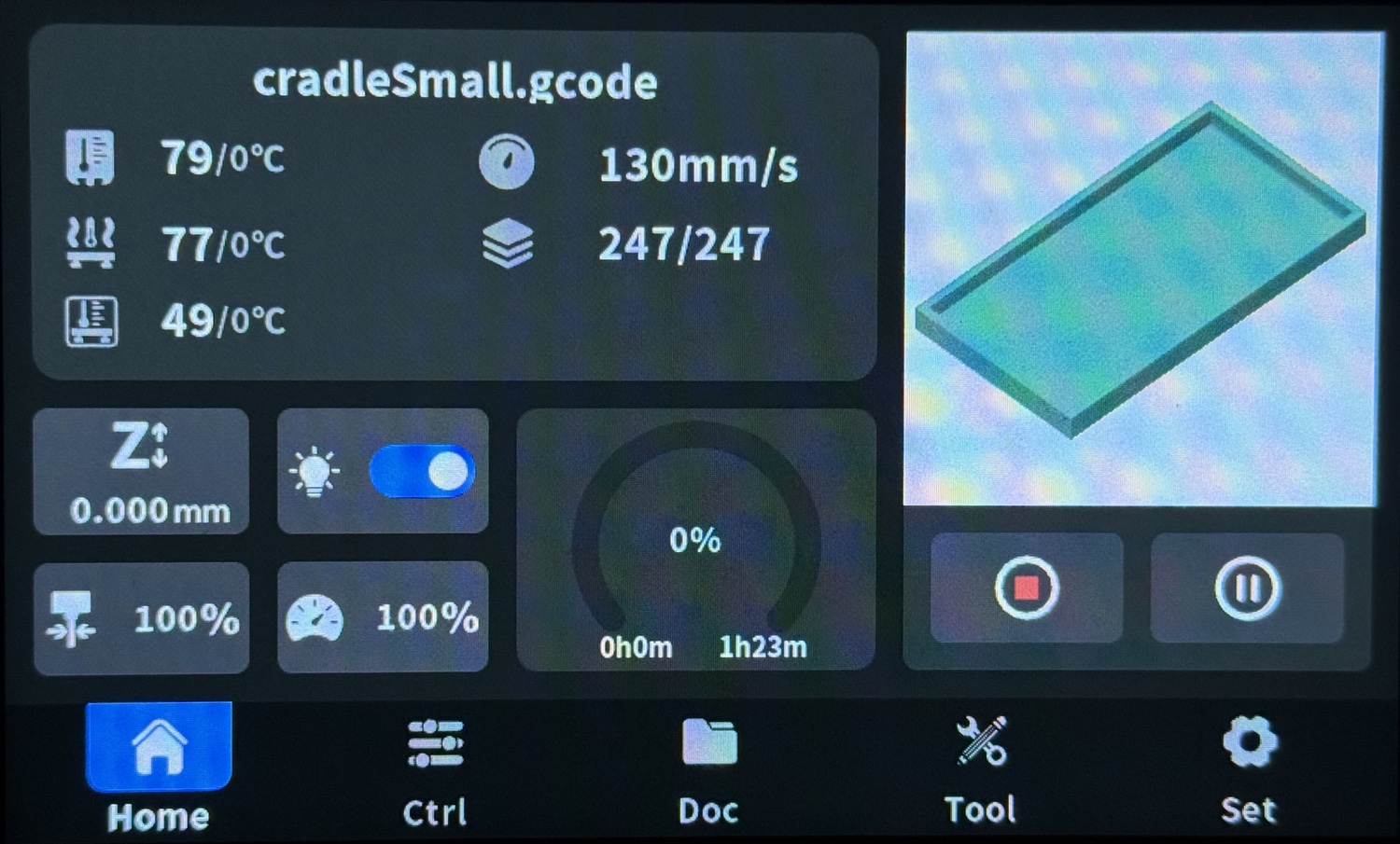
When the print starts, it will display a progress window. Usually, you will let the print run to completion, but if you need to pause or stop it, tap on those buttons. The screen also lets you monitor the temperatures; on the QIDI, these are the extruder, the chamber, and the bed, from the top down. You can also see how much time has elapsed (in minutes and as a percentage), and how much time remains. Most of my Jacob’s Staff prints take about 2 hours.
When printing is done, use a towel or a potholder (remember, the plate is 95°C, almost the boiling point of water!) to remove the plate, and flex it gently to release the parts. Pull the parts off and wash the plate with cool water to remove the adhesive. Dry the plate completely.
Remove any supports or brims from the parts. A screwdriver and needle-nose pliers can help, but the supports and brim generally come free with little effort. Fine sandpaper can smooth any rough edges.
Parting thoughts
These instructions are longer than I anticipated, but I erred on the side of completeness. Setting up each G-code file takes a few minutes, but once those are done, most of your time is spent waiting for prints to finish.